Experiment Overview
BELA uses the "direct-detection" (classical) approach to laser altimetry. High power pulses (50 mJ) at 1064 nm are emitted from a Q-switched Nd:YAG laser at 10 Hz. The emission time of each pulse is measured by a photodiode. The 60 urad wide beam is reflected from the surface (surface spot size = 20-50 m) and received around 5 ms later at a 20 cm diameter F/5 telescope. The image is refocussed onto a silicon avalanche photodiode through a narrow bandpass interference filter. The signal is then sampled and fed to a digital pulse discrimination electronics. This system determines the time of flight (and therefore range), the integrated pulse intensity, and its width. The data are passed to a digital processing unit which controls the operation and services the spacecraft interface. Onboard data compression and data storage are foreseen. The experiment requires significant baffling and thermal control but can operate over the dayside hemisphere (with only slightly reduced signal to noise) allowing optimum data acquisition over a minimum duration. BELA will provide 2 ns time resolution (30 cm range) which is commensurate with the expected knowledge of the spacecraft position. Optimum data return is expected at altitudes up to at least 1000 km above the surface. Samples will be acquired about every 250 m on ground-tracks separated by 25 km at the equator (crossing at the poles). Over the lifetime of the mission, data points will be 6 km apart (decreasing with latitude). The experiment will provide return pulse intensity and width information allowing an assessment of surface albedo and roughness at 20 m scales including in unilluminated polar craters.
Once on ground, acquired data will be converted into ranges initially with the support of orbit reconstructions. Data will be radiometrically calibrated to provide local surface roughness and albedo plots. Local topography maps will be derived almost immediately. Global topographic and shape maps and detailed products (e.g. centre of mass, centre of figure, oblateness) will require analysis of the full data set. Incorporation of the radio science and (possibly) stereo camera data will be required to derive global and regional terrain models, crustal thickness maps and the tidal flexing result.
BELA characteristics:

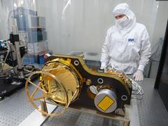
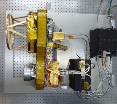
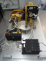
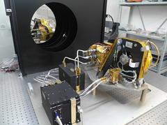
BELA has seven units which are identified on this CAD/CAM picture. The different components are described in more detail in the respective tabs below.
Electronics Unit (ELU)
The ELU is an electronics box which houses the Power Converter Module (PCM), the Digital Electronics Module (DPM) and the Rangefinder Electronics Module (RFM). It is being integrated by DLR-PF in Berlin.
Power Converter Module - PCM
The PCM takes the spacecraft power supply (which is nominally 28 Volts) and converts the voltage to several other voltages that BELA needs to drive its electronics. The board is redundant so that a failure of one PCM will not lead to a complete failure of the experiment. The PCM is being developed by the Instituto de Astrofisica de Andalucia (IAA) in Granada in cooperation with Spanish industry (CRISA).
Digital Electronics Module - DPM
The DPM is the on-board computer which controls the behavior of the experiment. It tells BELA when to fire, it flags the time when the laser was commanded to fire, it adjusts operational parameters, controls temperatures, reports on BELA’s status (housekeeping), collects the data from the receiver, generates telemetry packets and send them to the spacecraft. The DEB uses a LEON-2 processor which is tolerant to radiation. A software has been established which allows us to use a command language similar to the C language. The DEB is being developed by DLR-Berlin.
Rangefinder Electronics Module - RFM
The RFM is the board that evaluates the signals to determine a range to the target. The signals from the APD detector are digitized and then analysed to determine when the laser fired with respect to an onboard oscillator. The RFM knows roughly when to expect the return pulse to come back from the target. It opens a window (the range window) and collects data from the APD via the analogue electronics board (AEB). These data are digitized and analysed using a specific algorithm to determine the time delay between emission and reception with respect to the oscillator. The RFM then computes when to expect the next pulse and repeats the cycle.
The RFM has several modes depending upon how much data BELA can transmit to ground. In its simplest mode, the RFM simply returns the pulse delay plus some auxiliary data. It can however return the fully digitized range window and return this to the DPM.
The RFM needs software in a field programmable gate array (FPGA) which is used to identify the outgoing and the incoming pulses. The software also provides additional information (pulse width, pulse shape and pulse amplitude) to assist in the interpretation of the data.
The RFM has been developed by RUAG Space (Switzerland) under contract from the University of Bern.
Laser Electronics Unit (LEU)
The LEU controls the laser head box (LHB) and contains a large number of capacitors which pulse the laser diodes in the LHB. It takes 28 V from the spacecraft via the ELU to provide this pulse. The system can pump the system at 10 Hz.
The LEU is being developed by Cassidian Optronik under contract from the Max-Planck-Institut fuer Sonnensystemforschung in Göttingen.
Baseplate Unit (BPU)
The BPU comprises a baseplate (BP) upon which several elements are mounted. These are the laser head box (LHB), the receiver telescope (RTL), and the focal plane assembly (FPA).
Baseplate - BP
The BP is the optical bench which support the transmitter and the receiver. It is a lightweight sandwich board with inserts which is designed to be strong and rigid but light. Because of the large temperature range that BELA must support, the BP must also have a low coefficient of thermal expansion.
The BP is being designed and developed by RUAG Aerospace.

Receiver Telescope - RTL
The RTL is a Cassegrain-type (2 mirror) telescope with an aperture of slightly larger than 20 cm. The telescope must have a relatively small f/# to make the system lightweight. However, it must cope with an extended temperature range (including small thermal gradients) without deforming. The BELA chose to use beryllium for this task. Beryllium dust is highly toxic but all elements will be coated with (for example) copper so that they can be machined accurately without producing beryllium dust. Compared to high precision imaging, the tolerances on the surface shapes and roughnesses are slightly relaxed. BELA must collect photons onto a single detector – it doesn’t have to image. Nonetheless, the material is difficult to work with making the RTL a challenging piece of hardware.
The RTL is being designed and developed by RUAG Aerospace.

Focal Plane Assembly - FPA
The FPA contains an avalanche photo-diode (APD) detector. The detector is mounted on a board. In addition, the mechanical mounting supports fibre-optic cable attachments which are connected to the fibre-optic cables taking the light from the LHB to the APD. This serves to initiate the start pulse for the run-time measurement. The focal plane mechanics also support the back-end optics (BEO) which transfers light from the telescope to the detector.
Back-End Optics - BEO
The RTL is focused roughly at the apex of the primary mirror. The BEO images the focus point of the RTL and makes a parallel beam. An interference filter sits in the parallel beam to isolate light at the laser wavelength (1064 nm). The beam is then re-focussed onto the detector.
The BEO has been designed and developed by RUAG Aerospace in cooperation with FISBA Optik in St. Gallen.
Interference Filter
The interference filter which must fit in the BEO is required to have a narrow bandpass (to reject reflected sunlight from the planet) but must also have a high transmission at 1064 nm in order to give the instrument a strong enough signal. The BELA filter will have a bandwidth of 1.7 nm and a peak transmission of over 85%. A narrower filter would be possible but the wavelength of the laser is sensitive to temperature. Given the large temperature range over which BELA must operate, the filter must transmit the light from the laser over the full temperature range (including margins).
The interference filter is being produced by Barr Associates in cooperation with FISBA Optik and RUAG Aerospace.
Avalanche Photo-Diode - APD
All interplanetary laser altimeters to date have used infra-red enhanced silicon-based avalanche photodiodes – APDs. These detectors are 812 micron in diameter and have a quantum efficiency at 1064 nm of just over 30% with extremely low dark noise at operational temperatures (around 10°C). A batch were tested by UBE to identify their properties.
The APDs for BELA are derivatives of those produced for MOLA and MLA. They are being manufactured by PerkinElmer Opto-Electronics (now Excelitas) in Montreal, Canada under contract from the University of Bern and ESA.

Laser Head Box - LHB
The LHB comprises the laser itself and the laser diodes which excite the laser emission. The LHB has a beam expander on the front to make the beam more parallel.
The LHB is being developed by Cassidian Optronik under contract from the Max-Planck-Institut fuer Sonnensystemforschung in Göttingen.

Receiver Baffle Unit (RBU)
The RBU is designed to prevent the Sun from striking the RTL. BepiColombo is a nadir-pointing spacecraft. The optical instrument point continuously at the surface directly beneath the spacecraft. This orbit has major advantages for remote sensing because it allows continuous coverage. However, at Mercury it also has a disadvantage. The Sun can reach an angle of 38° from the boresight (the viewing direction of the BELA system) just before the spacecraft enters eclipse behind Mercury and just after the spacecraft exits eclipse. If this were not taken into account, sunlight could strike the telescope structure directly thereby heating the system to very high temperatures.
ELA requires that there is a 20+ cm hole in the spacecraft outer panel. This is so that the whole aperture of the telescope can see Mercury’s surface without vignetting. This hole however allows 300 W of direct sunlight to enter into the spacecraft under worst case conditions. This heat has to be removed. BELA does this in two ways.
Firstly, an all-reflective baffling system has been developed which rejects >90% of all light striking it at angles >38° back to space. This baffle (the RBU) is based on a concept first discussed by Kleinhans in 1976 and by Stavroudis in the early 1990s.
Secondly, the remaining heat (a maximum of 30 W for short periods) is dumped to a heat sink provided by the spacecraft and radiated to space via a spacecraft radiator.
The RBU has been designed and developed by the University of Bern with manufacture through Almatech in Lausanne.

Transmitter Baffle Unit (TBU) and Straylight Protection Unit (SPU)
The TBU is similar to the RBU but with two significant differences. On the one hand, the TBU is considerably smaller because the diameter of the outgoing laser beam is much smaller than the RTL primary mirror. This makes its construction easier. On the other hand, the TBU needs to contain a filter. This filter is required to reject reflected sunlight from Mercury in much the same way as the interference filter in the BEO but for a very different reason. The LHB contains a beam expander to broaden the laser beam and make it more parallel. In reverse, however, this beam expander can focus light from the surface of Mercury onto the laser providing potentially dangerous light levels for the system. The filter in the TBU is used to reject this light. Its inclusion in the TBU makes design of the system significantly more complicated.
The TBU and SPU are being designed and developed by DLR-Berlin.

Analogue Electronics Unit (AEU)
The Analogue Electronics Unit controls the APD detector and has been designed by Syderal AG in Gals.


